AI Hardware Parts
GPU & ASIC Liquid Cold Plates
Direct-to-chip thermal hardware with contact flatness and liquid integrity controlled together.
Direct answer
GPU and ASIC cold plates must be quoted as thermal assemblies, not generic milled plates. The package contact map, flatness and roughness, channel geometry, joining method, coolant, cleaning standard and leak-test threshold all affect the manufacturing route and inspection plan.
Components and applications
- GPU accelerator cold plates
- ASIC and inference-module cooling lids
- Multi-chip module thermal plates
- Cold-plate development coupons and fixtures
Recommended manufacturing route
- 01
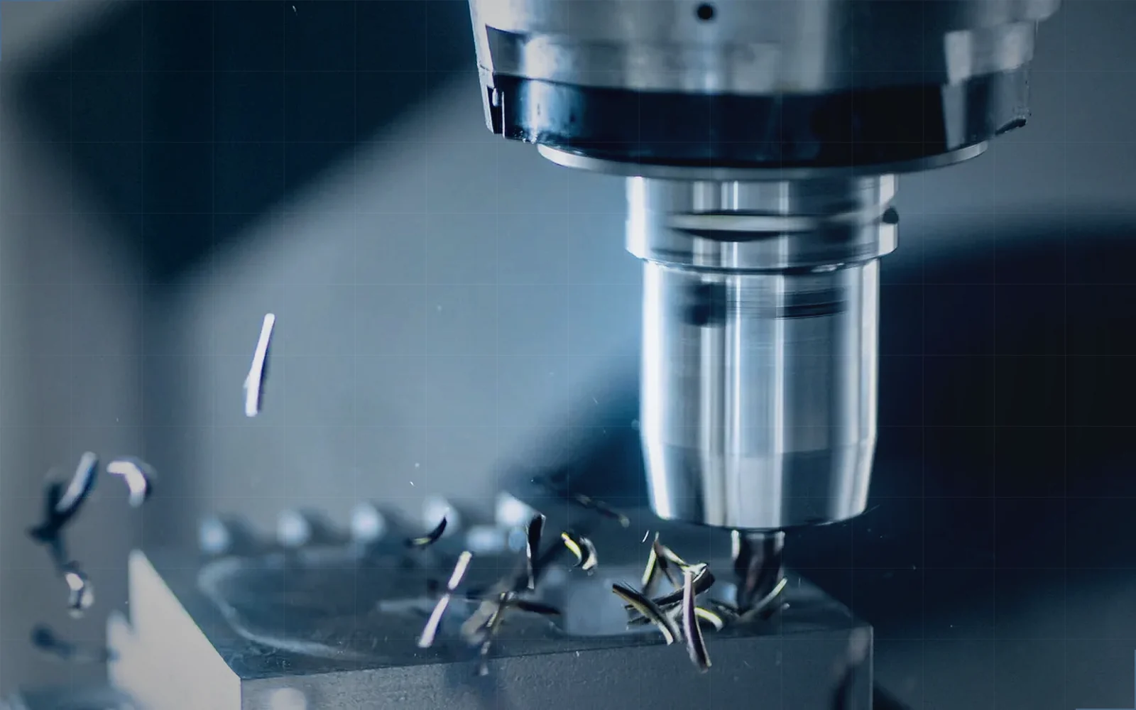
Machine contact datums and channel geometry from stable stock.
- 02
Control burrs and channel cleanliness before closure.
- 03
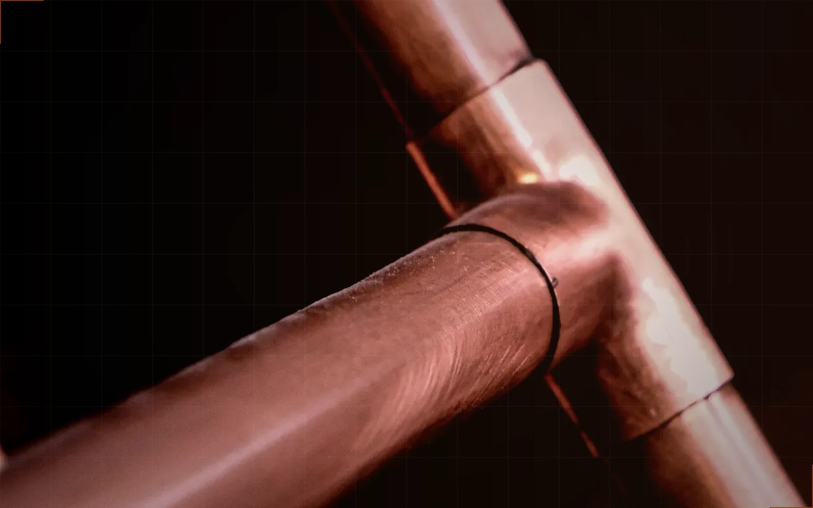
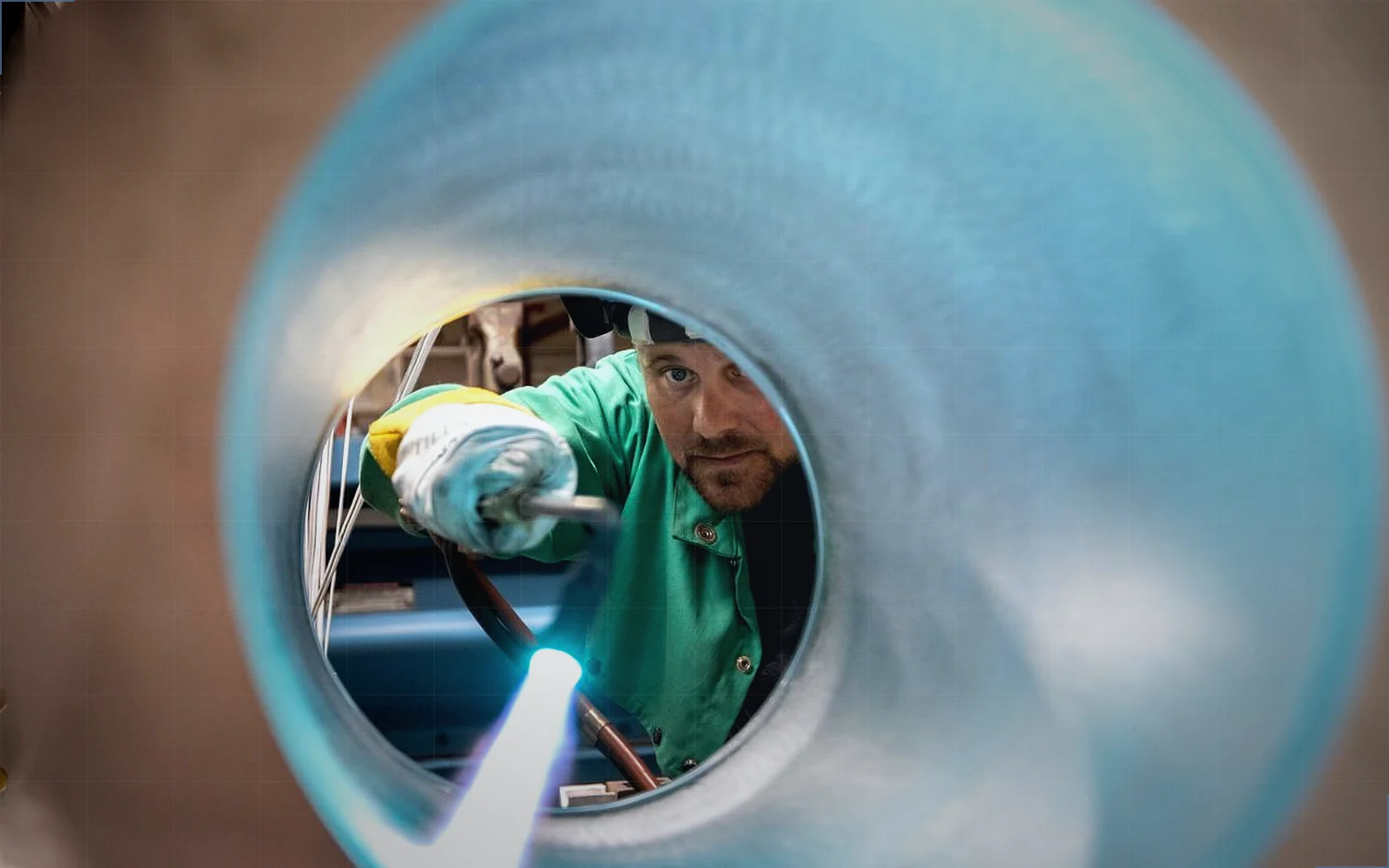
Join or assemble the cover to the specified process.
- 04
Verify flatness, cleanliness and liquid integrity after joining.
Drawing and RFQ controls
| Control | Quote guidance |
|---|---|
| Die contact map | Identify every package height, keep-out zone and controlled contact surface. |
| Channel geometry | Define minimum land, depth, corner radius and permissible internal burr. |
| Joining distortion | Apply final flatness after brazing, welding or cover assembly if that is the functional state. |
Related processes
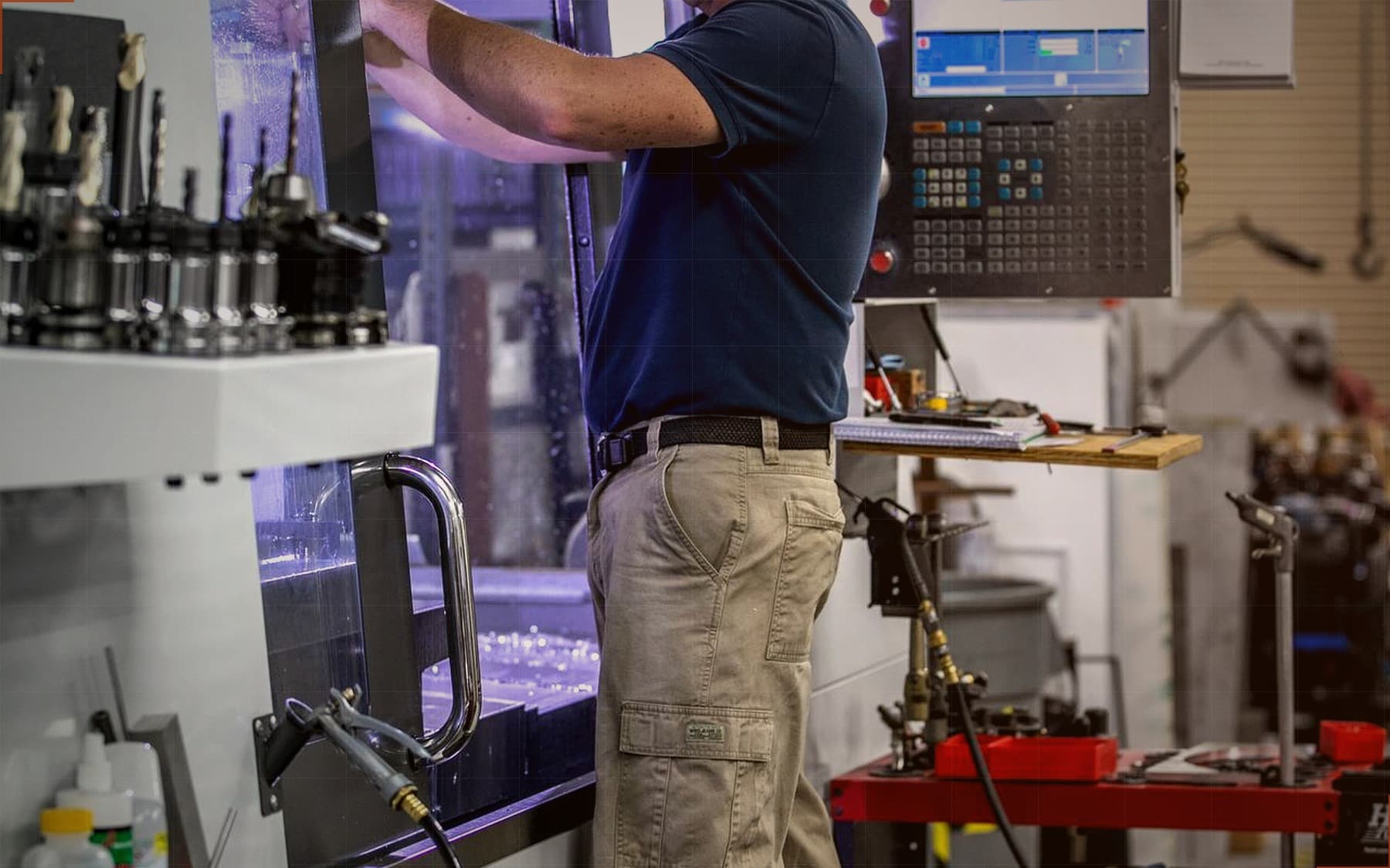
CNC Milling
3- and 4-axis vertical machining for housings, brackets, manifolds and structural parts.
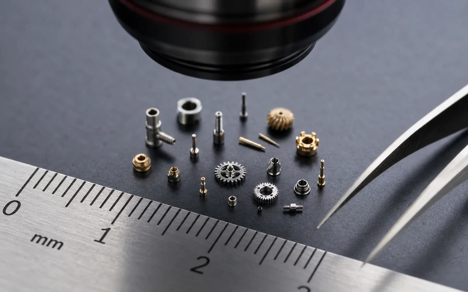
Micro Machining
High-speed spindles and Ø0.1 mm tooling for features below 1 mm and watch-scale parts.
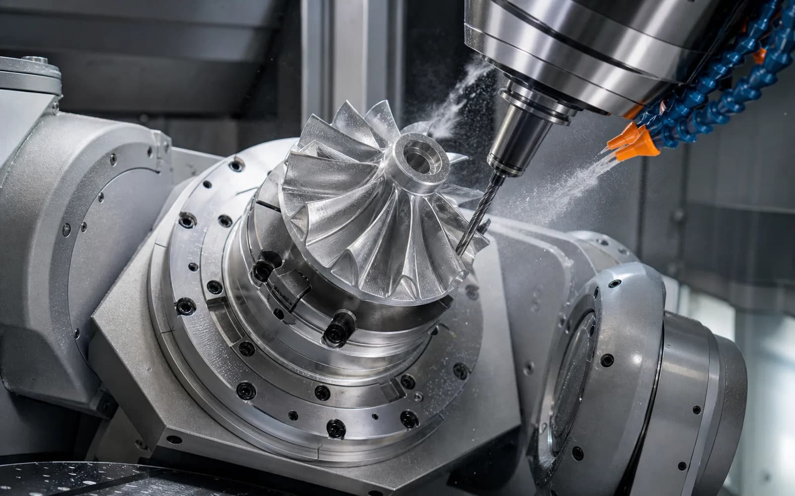
5-Axis Machining
Simultaneous 5-axis machining for impellers, freeform surfaces and compound-angle features.
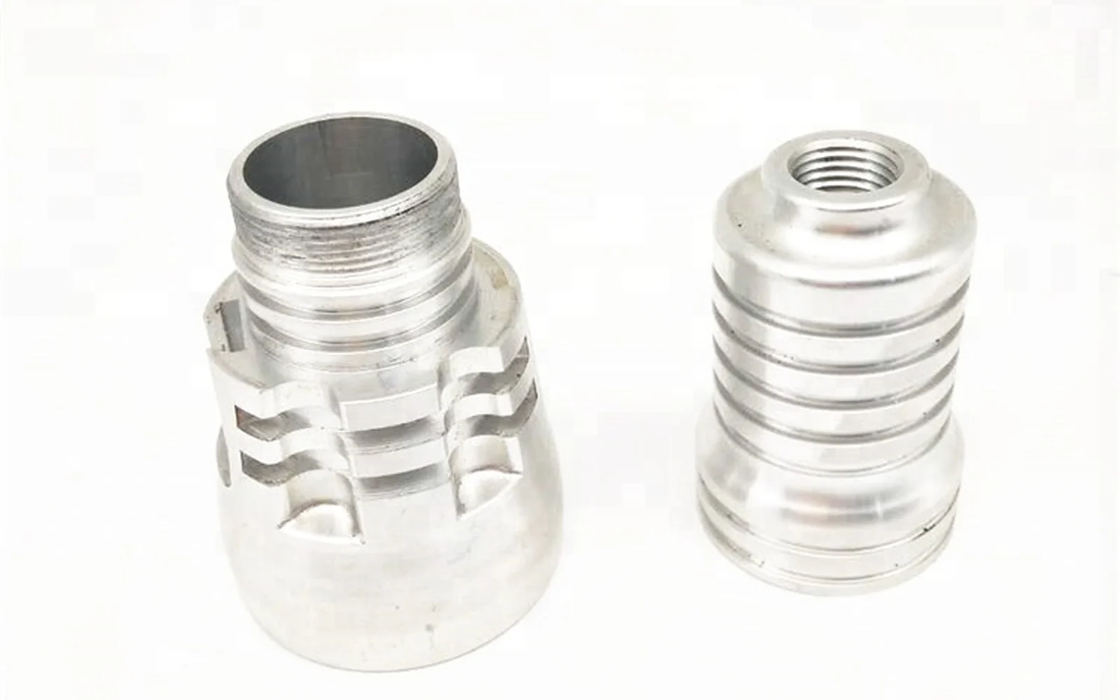
Prototype Machining
Functional prototypes in production-grade materials, shipped in days with DFM feedback included.
Compatible finishes
Inspection to define before production
- Contact-surface flatness and roughness map
- Channel and seal geometry inspection before closure
- Defined pressure-decay or helium leak-test record after joining
Applicable standards and documentation
- Customer thermal stack specification
- Contact load, TIM and package limits remain customer-defined.
- Coolant cleanliness specification
- Particle and residue limits must be agreed before manufacturing.
Related guides and hubs
GPU & ASIC Liquid Cold Plates buyer questions
01What files are needed to quote a GPU cold plate?
Send the assembly STEP, controlled part drawings, package contact map, channel and joining definition, coolant, test condition, quantity and inspection outputs.
02Should flatness be checked before or after joining?
The functional requirement normally applies after the final joining and finishing process. The drawing should state the condition explicitly because joining can move the contact surface.
Other ai hardware parts solutions
AI Server Liquid-Cooling Manifolds
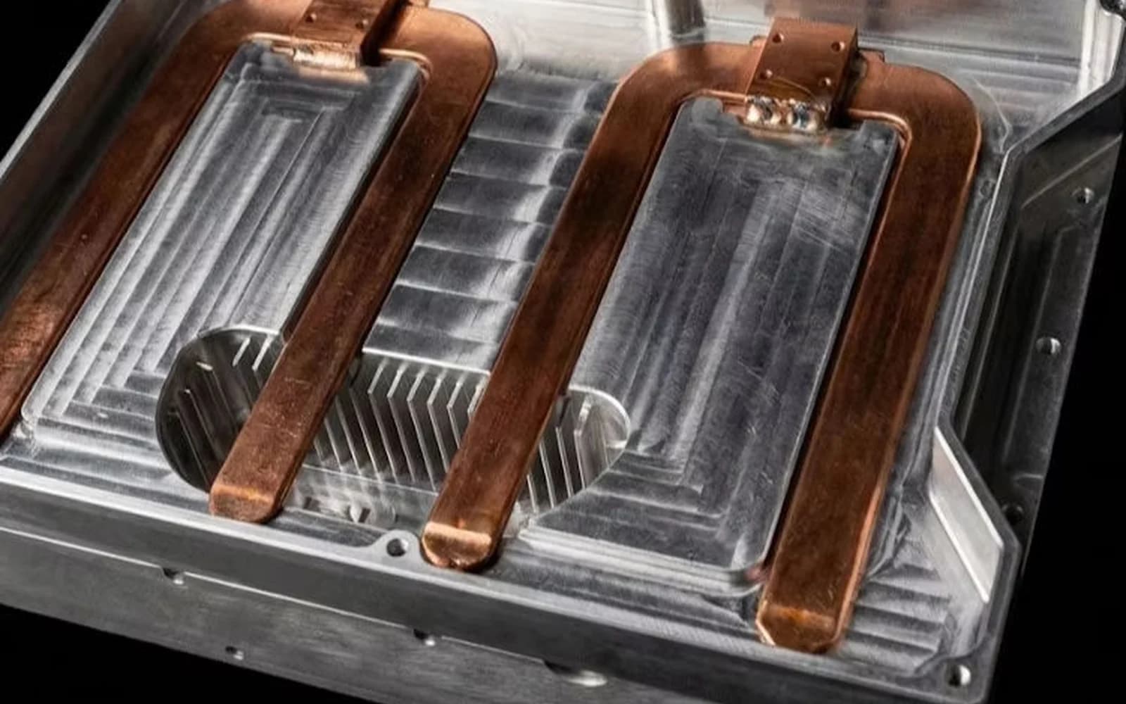
Clean, leak-controlled distribution blocks for server and rack liquid loops.
Edge AI Enclosures & Server Chassis
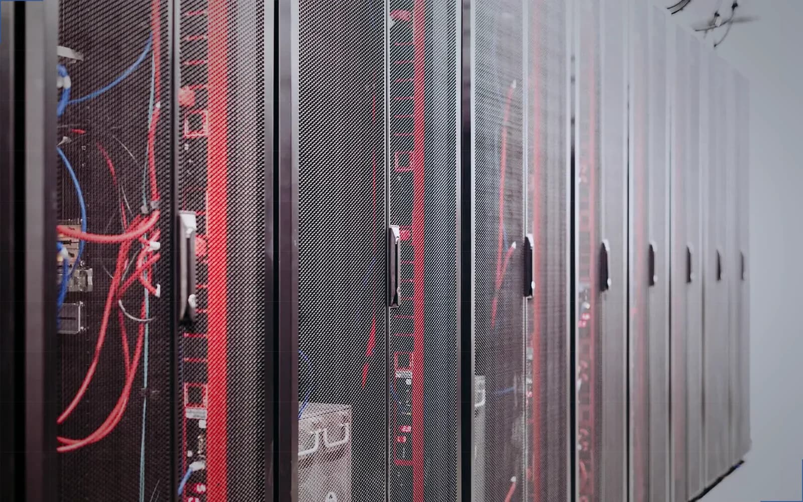
Rigid compute enclosures that align boards, connectors and thermal hardware.
AI Server Busbars & Power Hardware
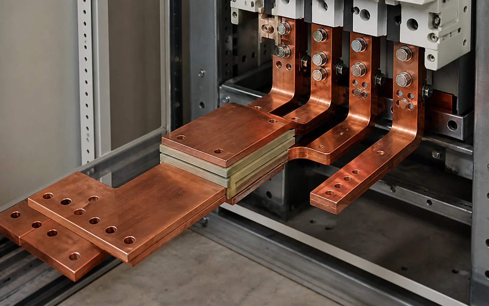
Compact high-current conductors with protected electrical contact geometry.
Have a part in mind?
Upload CAD or drawings. Eligible CNC work gets an instant estimate; other processes move to engineer review. NDA-protected from the first byte.
Start an RFQ